
Overview
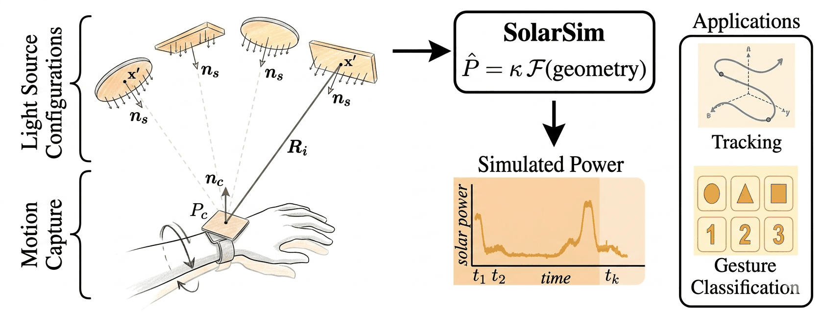
The SolarSim Interactive Simulator is a tool for visualizing and analyzing power harvesting from wearable solar cells under controlled lighting conditions. It provides radiometric simulation with two physics-based models (Orientation Aware and Parallel Disk), configurable light source position and diameter with real-time visualization, and export functionality for simulated power traces in CSV format.
The fundamental power equation:
where is harvested power, is the scaling factor, is the view factor function, and is noise.
View factor : The fraction of radiant energy leaving the light source surface that strikes the solar cell surface directly. It depends purely on the geometry—the relative position, orientation, and size of the two surfaces.
For background on view factor theory, see Modest [1] and Bergman et al. [2].
Current assumptions: single dominant emitter, uniform irradiance over cell, and cell positioned below the lamp ().
Quick Start
Everything in the simulator connects to one equation. Hover over each symbol to see what it controls:
Power Output
The simulated power curve (purple) in the chart — this is the prediction target.
κ (Kappa)
Scaling factor combining cell efficiency η, cell area A, and light intensity I₀.
View Factor
Choose Orientation Aware or Parallel Disk model.
Geometry
Lateral offset (a) and vertical separation (H) from trajectory and light position.
Power Output
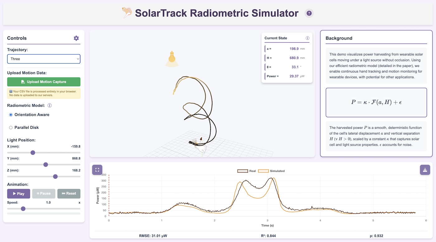
Controls Panel
| Control | Description |
|---|---|
| Trajectory | Select from preloaded trajectorys or choose "Custom" to draw your own |
| Upload Motion Capture | Load a CSV file with motion capture data (see Input Trajectory Format) |
| Radiometric Model | Choose between Orientation Aware and Parallel Disk models |
| Light Position (X, Y, Z) | Adjust the 3D position of the light source in millimeters |
| Animation Controls | Play, Pause, and Reset the trajectory animation |
| Speed | Adjust animation playback speed (0.1x to 10x) |
3D View
- Orbit: Click and drag to rotate the view
- Zoom: Scroll wheel to zoom in/out
- Pan: Right-click and drag to pan
- Trajectory color: Indicates relative power (dark = low, bright = high)
Current State Panel
With more than one emitter in the scene, , and are reported relative to the primary emitter — the first one that is enabled. Power is always the total across every enabled emitter, so it reflects the whole scene rather than the primary source alone.
| Variable | Description |
|---|---|
| Lateral displacement from light source axis (mm) | |
| Vertical distance from light source (mm) | |
| Cell tilt angle relative to light direction (degrees) | |
| Power | Simulated instantaneous power (µW) |
View Factor ℱ
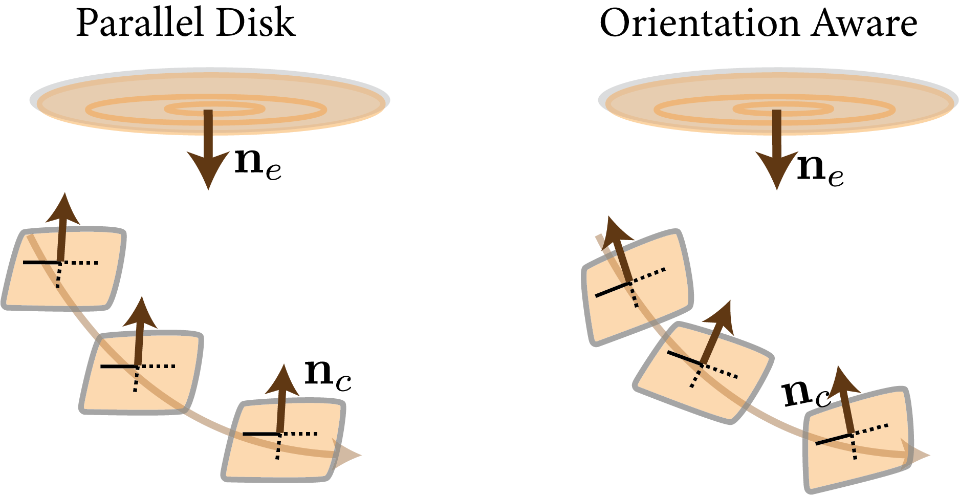
The simulator supports two radiometric models for computing the view factor between the light source and the solar cell.
Parallel Disk Model
This simplified model assumes the solar cell is always parallel to the light source disk (i.e., facing directly upward). It ignores cell tilt.
where is the vertical separation (cell below lamp, ), is the lateral offset, is the disk diameter, and are polar coordinates on the disk.
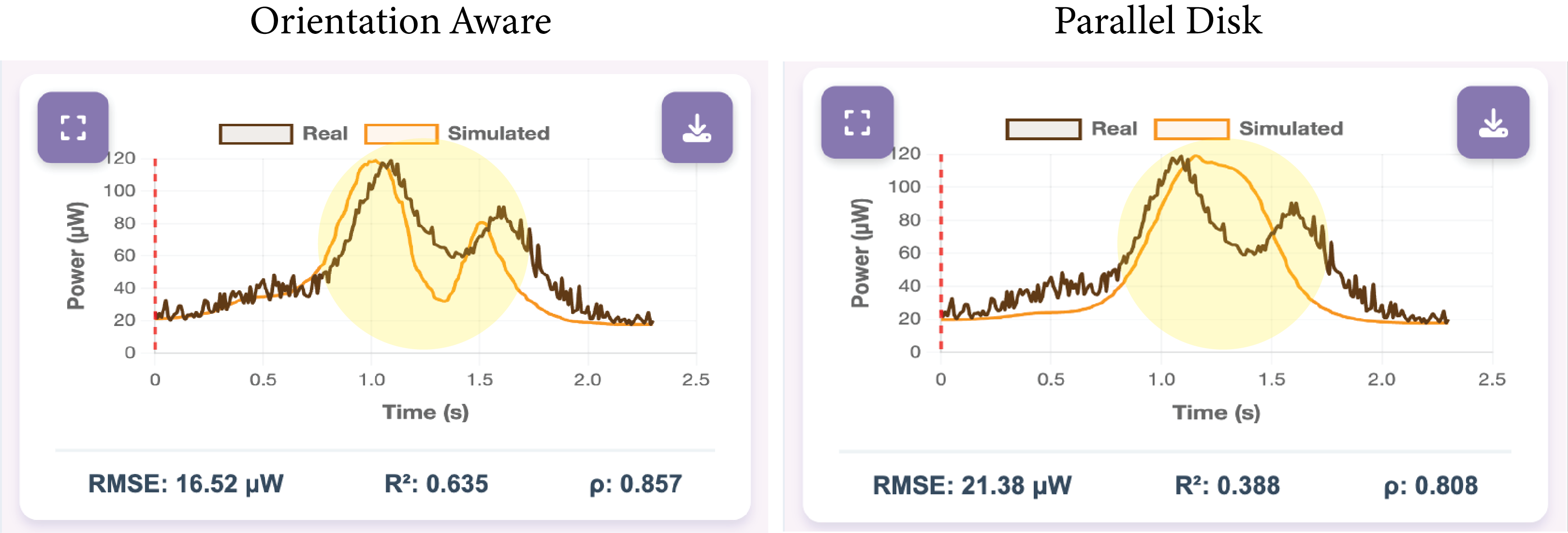
Best for: Overhead lighting with minimal hand tilt. Requires: Position data only (no cell normals needed).
Orientation Aware Model
This model accounts for the tilt angle of the solar cell relative to the light source. It uses the full radiometric kernel that considers both the emitter and receiver orientations.
where is the parallel disk view factor (Eq. A.5) and is the angle between the cell normal and the direction to the light.
Full disk integration over the emitter disk of diameter , where is the vector from emitter patch to cell , is the emitter normal, and is the cell normal.
Best for: Tilted or rotating cells where orientation matters. Requires: Position + cell normal vectors.
To switch between approximate and exact modes, see Advanced Settings.
Scale κ
The scaling factor converts the dimensionless view factor into actual power values. It encapsulates all the physical constants and calibration factors of the system.
where is the solar cell efficiency, is the cell area, and is the effective irradiance from the light source.
In a multi-emitter scene each source carries its own , because two lamps may differ in intensity or colour temperature while
sharing the same geometry. This simulator fits a single to the total view factor when scaling against a reference
trace, which is the right choice when the sources share a spectrum and the quantity of interest is trace shape. Fitting per-emitter
by non-negative least squares is what the pysolarsim package does when calibrating a real environment.
Configuration Options
Manual Input
Enter a custom value directly. Useful when you have a known calibration value from prior experiments or want to explore how scaling affects the output.
Estimate from Physical Parameters
Estimate from physical properties when actual values are known:
- Solar cell efficiency (typical: 10-25%)
- Cell area in cm²
- Light source power in Watts
Fit from Real Data
When measured power data is uploaded alongside trajectory data, the simulator can automatically fit using least-squares regression:
where indexes over trajectory samples, is the measured power at sample , and is the computed view factor at that position.
Why this option? This is useful for validating the model against experimental data or calibrating for a specific hardware setup. It requires real power measurements, which are not always available in simulation-only workflows.
Advanced Settings
Access advanced settings by clicking the gear icon in the Controls panel header.
Simulation Method (Orientation Aware)
| Method | Description |
|---|---|
| Fast (Approximate) | Point source approximation with correction |
| Exact | Full disk integration using Simpson's rule |
Light Source Properties
The simulator supports up to four emitters in one scene. Use Add Emitter in the emitter panel to introduce another source; each row carries its own geometry, position, orientation and enable toggle, and each is drawn in a distinct colour in the 3D view.
- Shape — Circular (desk lamps, downlights,
spotlights) or Rectangular (LED panels, troffers, light strips).
Circular emitters are sized by diameter
D; rectangular ones by widthWand lengthL, all in millimetres. - Position — X, Y and Z of the emitter centre, in the motion-capture coordinate frame.
- Tilt / Azimuth — orientation of the emitter face. Tilt 0° points straight down; azimuth rotates the tilt direction.
- Enable toggle — keeps an emitter in the scene but out of the sum, which is useful for isolating one source's contribution.
Total power is the sum of the per-emitter contributions: irradiance from independent sources adds linearly at the cell, so adding an emitter never changes another one's contribution. There is no inter-emitter occlusion or interreflection in the model. The exported CSV records each emitter's shape, position, dimensions and orientation in its header.
- Diameter (mm): The diameter of the light source disk. Default is 100mm. Larger values spread the light over a wider area.
Numerical Integration (Exact Mode Only)
These settings control the Simpson's rule grid for disk integration:
- Radial divisions (): Number of divisions along the radius (default: 20)
- Angular divisions (): Number of divisions around the circumference (default: 40)
Higher values increase accuracy but slow down computation. Total integration points = .
Visualization
- Color threshold (samples): For trajectories with more samples than this threshold, the drawing animation uses a uniform color instead of power-coded colors for better performance. Default: 4000.
Input Trajectory Format
The simulator accepts CSV files with motion capture data. Several column naming conventions are supported.
Supported Formats
Format 1: Leap Motion Raw
Direct output from Leap Motion SDK:
time, leap_palm_x, leap_palm_y, leap_palm_z, leap_palm_normal_x, leap_palm_normal_y, leap_palm_normal_z, v_dc, i_dc
Format 2: Simplified Leap
Shortened column names:
timestamp, palm_pos_x, palm_pos_y, palm_pos_z, palm_normal_x, palm_normal_y, palm_normal_z, power
Format 3: Generic XYZ
Minimal format with positions and normals:
x, y, z, nx, ny, nz, power, time
Column Descriptions
| Column | Required | Description |
|---|---|---|
x, y, z (or variants) |
Yes | Palm/cell position in millimeters |
nx, ny, nz (or variants) |
Optional | Cell normal vector (unit vector). Required for Orientation Aware model. |
v_dc |
Optional | Measured voltage (V) |
i_dc |
Optional | Measured current (A). Power = v_dc × i_dc |
power |
Optional | Direct power measurement (alternative to v_dc/i_dc) |
time or timestamp |
Optional | Time stamp for each sample |
Example CSV
time,leap_palm_x,leap_palm_y,leap_palm_z,leap_palm_normal_x,leap_palm_normal_y,leap_palm_normal_z,v_dc,i_dc
0.00,-45.2,655.8,120.4,0.15,0.92,-0.36,0.48,0.00052
0.01,-44.8,655.1,121.3,0.14,0.93,-0.35,0.49,0.00051
0.02,-43.9,654.2,122.1,0.13,0.94,-0.33,0.47,0.00053
...
Notes
- All position values should be in millimeters
- Normal vectors should be unit vectors (length ≈ 1)
- The cell normal points away from the palm (opposite to palm normal)
- Files are processed entirely in your browser — no data is uploaded to servers
Export Format
The file begins with comment lines recording the scene that produced it: one line per emitter giving its shape, position, dimensions, orientation and enabled state, so an export can be traced back to an exact configuration.
When you export simulation results, the CSV contains:
timestamp, simulated_power_W, a_mm, H_mm, theta_deg
| Column | Description |
|---|---|
timestamp |
Time in seconds |
simulated_power_W |
Simulated power output in Watts |
a_mm |
Lateral offset from light source (mm) |
H_mm |
Vertical separation from light source (mm) |
theta_deg |
Cell tilt angle in degrees (Orientation Aware model only) |
The export file also includes metadata comments at the top with trajectory name, model type, light position, and κ value if applicable.
Citation
If you find this work useful, please cite:
@inproceedings{ghalwash2026solarsim,
  title     = {SolarSim: Physics-Based Simulation of Wearable Solar Harvester Signals for Motion Sensing},
  author    = {Yasien Ghalwash and Abdelwahed Khamis and Sara Khalifa and Moid Sandhu and Raja Jurdak},
  booktitle = {Proceedings of the ACM on Interactive, Mobile, Wearable and Ubiquitous Technologies},
  year      = {2026}
}

@inproceedings{ghalwash2026solartrack,
  title     = {SolarTrack: Exploring the Continuous Tracking Capabilities of Wearable Solar Harvesters},
  author    = {Yasien Ghalwash and Abdelwahed Khamis and Moid Sandhu and Sara Khalifa and Raja Jurdak},
  booktitle = {Proceedings of the 24th IEEE International Conference on Pervasive Computing and Communications (PerCom)},
  year      = {2026}
}
References
- Modest, M. F., & Mazumder, S. (2021). Radiative Heat Transfer. Academic Press.
- Bergman, T. L., Lavine, A. S., Incropera, F. P., & DeWitt, D. P. (2017). Fundamentals of Heat and Mass Transfer (8th ed.). Wiley. — Chapter 13: Radiation Exchange Between Surfaces.
Contact
For questions or feedback, open an issue on GitHub or email abdelwahed.khamis@data61.csiro.au.